Application
Additionally, the system module structure has increased few times the system reliability, because any possible system failure within the scope of one module with OSA controller would not destabilize the work of the others. One from among OSA controllers at SAT rack is declared as the master controller.
SAT system may also cooperate with other devices – such as, for instance, methane-detecting, fire, telephone exchanges, visualization systems and other. These devices are linked to the outside RS485 main conduct through BUZ buffers of outside equipment or via Ethernet.
SAT system is equipped with four acoustic rails what enables the simultaneous work of four dispatchers. Additional computers, without conversation option, may be hooked up with the status of a watch post.
Versions
SAT–A – (emergency) version equipped only with programmable intrinsically safe signalling device – telephones type PST
SAT/N–A – (emergency, non-intrinsically safe) version equipped only with programmable signalling device – telephones type PST-N
SAT–T – (telephone) version equipped only with intrinsically safe telephones type TIG-S
SAT/N–T – (telephone, non-intrinsically safe) version equipped only with industrial telephones type TPN-S
SAT–Z – (integrated) version equipped with both intrinsically safe signalling devices – telephones PST and intrinsically safe telephones TIG-S
SAT/N–Z – (integrated, non-intrinsically safe) version equipped with both signalling devices – telephones PST-N and telephones TPN-S
Cooperation
With all types of telephone exchanges.
Power supply
Buffered – 48 or 60V DC.
Capacity
- any, in modules of 16 NN
- standard – n x 192 NN
Surface equipment
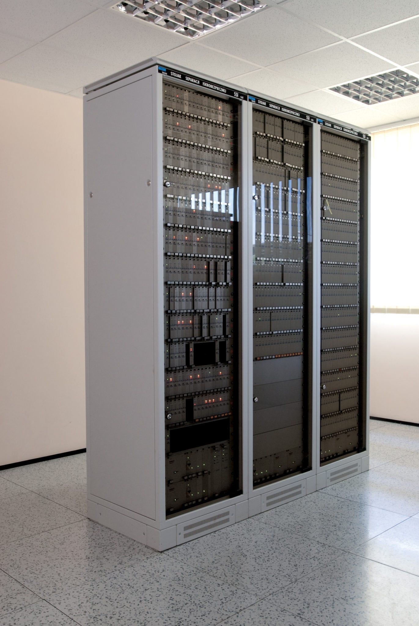
- SSI-SAT line – separating rack
- computer dispatcher’s posts with conversations recorders
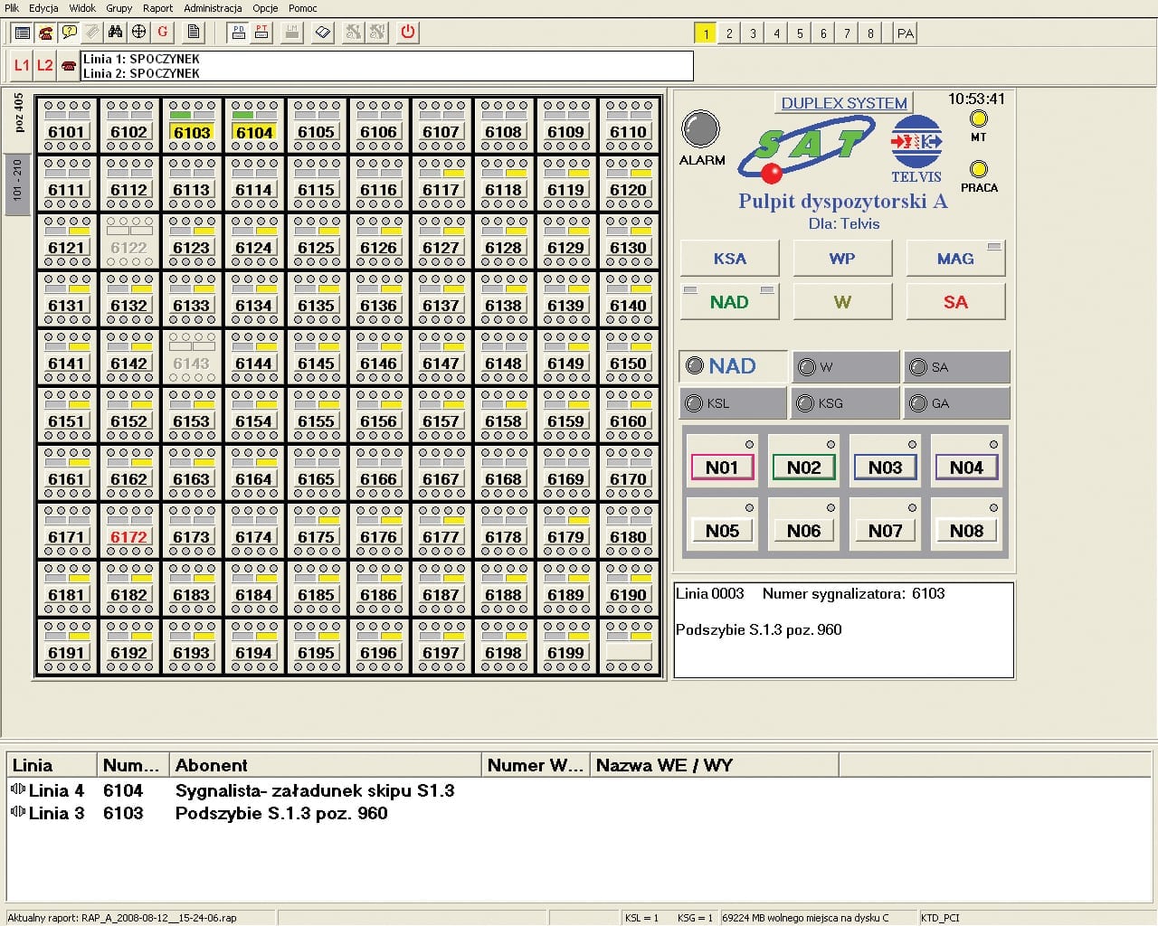
- PD-SAT dispatchers’ control desks – up to 3 pieces
- SU-SAT maintenance post – 1 piece
Underground equipment
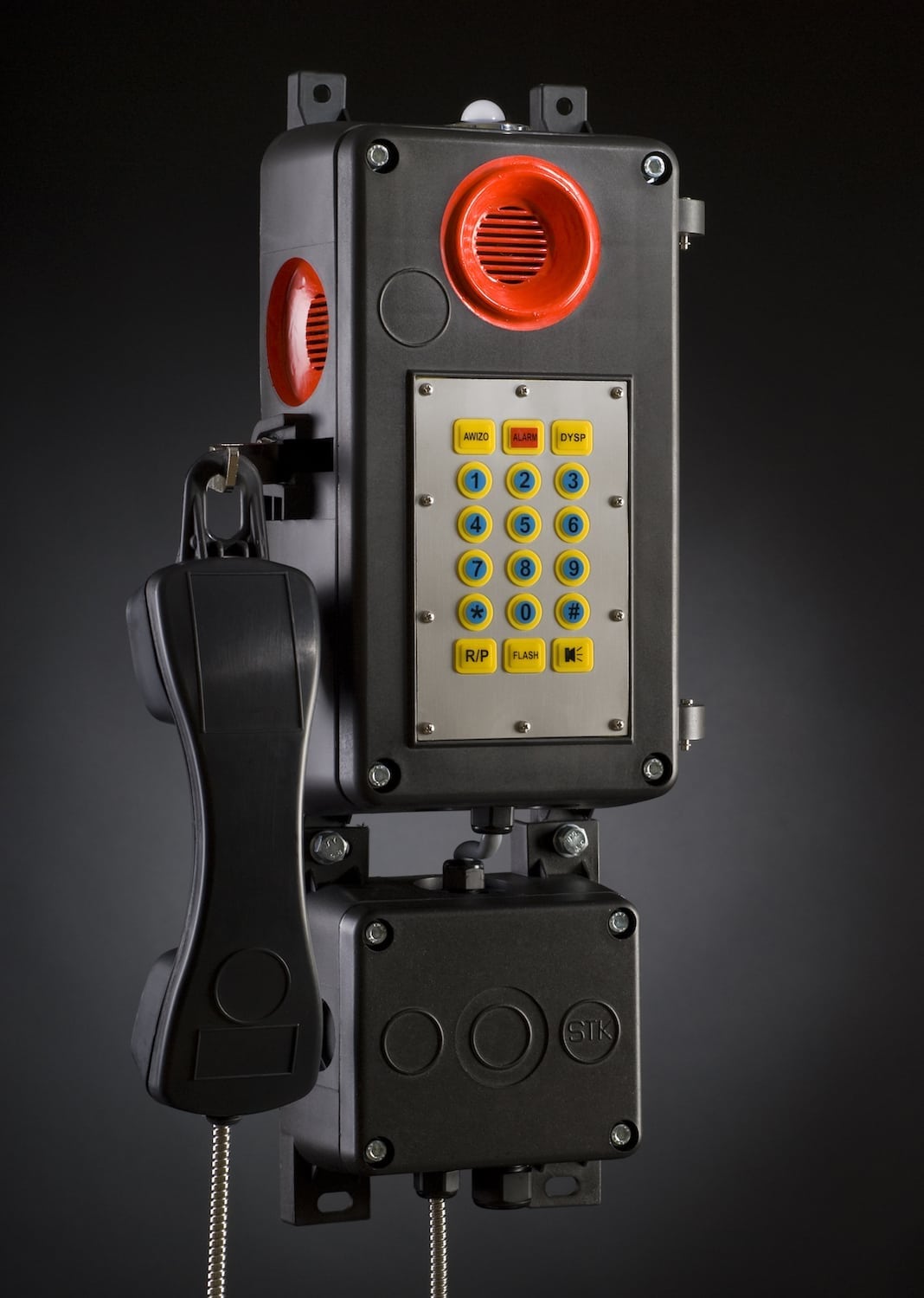
- PST programmable loudspeaking telephones
- TIG intrinsically safe telephones
- MCCD-01 underground controllers (option)
SAT technical data
| SSI-SAT racks feeding | 48 V DC buffered |
| Power drawn form the supply source 48 V | 3 W x No. Of subscribers |
| Power supply of dispatchers’ desks | 230 V AC guaranteed |
| Internal power supply | +5, +12, -48 V |
| Maximum number of dispatcher’s communication lines | 1040 |
| Levels of conversation signals | 0.775 V (0dBm) |
| Maximum voltage in non-spark safe subscriber’s line | 41 V DC |
| Maximum voltage in intrinsic subscriber’s line | 41 V DC |
| Current efficiency of exchange subscriber’s equipment | 30 mA |
| Current efficiency of output circuit of LPI unit | 35 mA |
| Current efficiency of output circuit of LPI unit | ExiaI/IIB acc. to PN-EN50014 |
| Protection degree of PST casing | IP65 |
| Protection degree of MCCD-01 casing | IP54 |
| Operating temperatures range | from +5 °C to +40 °C |
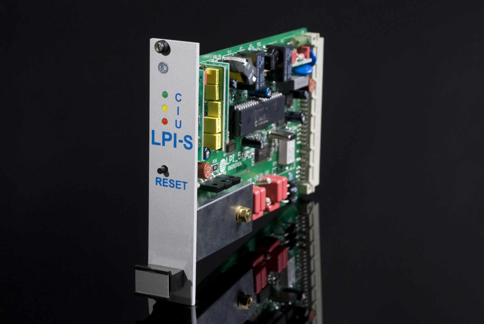
Electrical parameters of line units LPI and LM
| Current from -48 V input | max. 50 mA |
| Current from +12 V input | max. 50 mA |
| Telephone line input resistance | max. 600 Ω |
| Telephone line impedance for 1000 Hz | 600±50 Ω |
| Direct voltage at unloaded line output | max. 41 V |
| Maximum value of direct current in line | 45 mA |
| Level of DTMF signal at line output | 4±1 dB |
OSA technical data
| Power supply voltage | +5 V |
| Power consumption | max. 100 mA |
| RS485 main conduct protocol | MODBUS |
Parameters of KTD – computer dispatcher’s communication card
| Power supply voltages | +5 V i +12 V |
| Current from +5 V/12 V input | max. 100 mA/100 mA |
| Number of control circuits | 1 |
| Number of telephone line inputs | 2 |


